** We’re moving to a new office on Friday, May 31st, 2013. Orders placed after 10am CST tomorrow (5/31) will ship Monday! **
If you’ve assembled NwAvGuy’s Objective2 in the past year, you must have noticed that its power jack is discontinued. Alternatives to Kobiconn 163-7620-E do not fit.
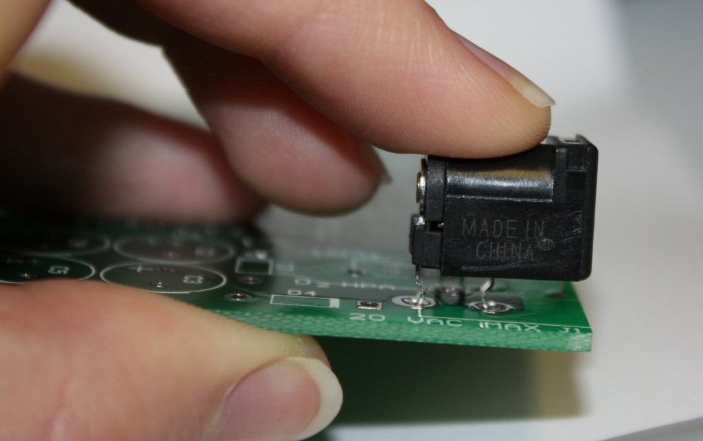 Substitute power jack for O2. Does not fit.
NwAvGuy last reached out to us on July 1, 2012 before mysteriously disappearing. Two months earlier, he’d discussed revising the O2 PCB. The discussion is archived for those interested:
From:Northwest AvGuy
Sent: Tuesday, May 01, 2012 12:30 PM
To: John Seaber
Subject: John: O2 Power JackHave you found an alternate power jack for the O2, are you modifying jacks to fit, or do have enough of the old ones for now? I’m getting more questions about the discontinued jack and trying to decide what the best solution is.
If I revise the PCB artwork I would fix the jack footprint and move the via under the corner of the gain switch. Are you aware of any other necessary board revisions?
On Tue, May 1, 2012 at 11:57 AM, JDS Labs Inc. wrote:
We source unique parts in large quantities, so we have enough power jacks to last all year.
Kobiconn 163-179PH-EX is close. Dimensions aren’t a perfect match to 163-7620-E, but it should fit existing O2 boards and front plates [Edit: 163-179PH does not fit]. Breaking mechanical compatibility with the original board/plates would be a mess.
No other revisions should be necessary!
On Tue, May 1, 2012 at 2:08 PM, Northwest AvGuy wrote:
Thanks for the reply. Yeah, I have a sample of the 179PH already and, as I posted on the O2 Summary comments, two of the tabs are a bit too big. A revised board shouldn’t change form, fit, or function of the assembled board.
Just beware before ordering a large number of PCBs the artwork may be revised so you might want to check in with me first.
We believed NwAvGuy would eventually update O2. Now that almost a year has elapsed, we can only hope he’s doing okay.
We’ve spent the past few months seeking substitute power jacks. No success. Jack manufacturer Kycon quoted a custom part, with tooling and minimum order quantity totaling $25k-$100k. Not worth it! The last thing we want to do is violate NwAvGuy’s work by disregarding the O2’s no-derivatives license. We’ll gladly respect any wishes he may have if he’s able to return in the future. Until that time comes, we’ve decided it’s time to proceed with NwAvGuy’s intention of sustaining O2 as a viable DIY project. That means the O2 PCB must accept common power jacks.
NwAvGuy only supplied Gerbers for the O2, which makes the design nearly impossible to modify without re-drawing the schematic and PCB from scratch (definitely unacceptable).
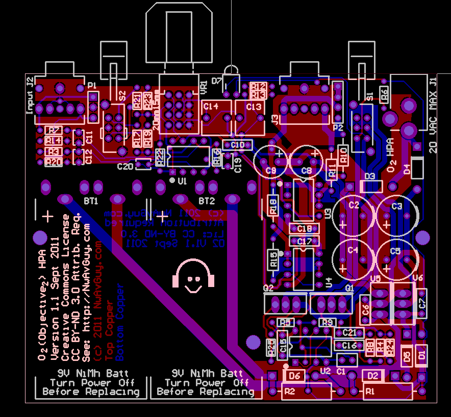
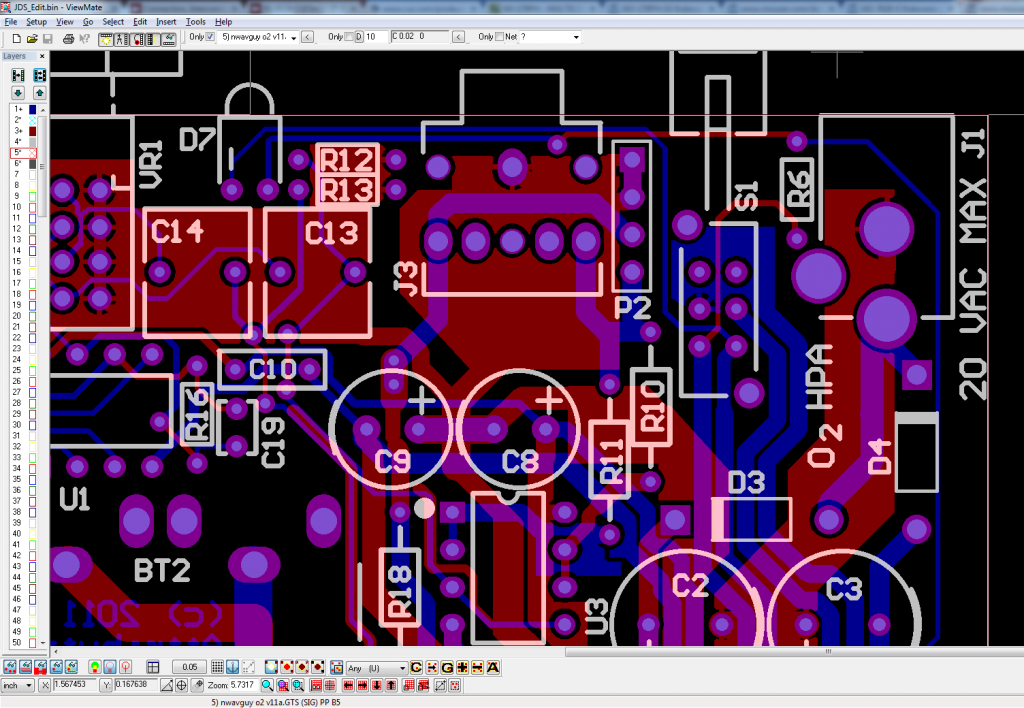
Zooming in on the power jack (J1), you can see that plenty of copper surrounds its 2.3mm holes:
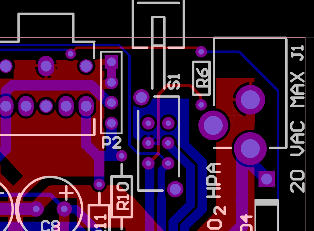
Most power jacks have pin widths of 3.0mm, instead of the small 2.3mm pins used by 163-7620-E. So, we only need to increase hole diameter at J1 by 0.7mm.
NwAvGuy left us with wonderful documentation. You can find this table in the O2 readme, and tool “T8” looks like the drill bit relevant to jack J1:
| Tool | Hole Size | Hole Type | Hole Count Plated |
| T1 | 28mil (0.7112mm) | Round | 104 |
| T2 | 32mil (0.8128mm) | Round | 44 |
| T3 | 42mil (1.0668mm) | Round | 23 |
| T4 | 53mil (1.3462mm) | Round | 24 |
| T5 | 55mil (1.397mm) | Round | 8 |
| T6 | 62mil (1.5748mm) | Round | 12 |
| T7 | 68mil (1.7272mm) | Round | 12 |
| T8 | 91mil (2.3114mm) | Round | 3 |
| T9 | 125mil (3.175mm) | Round | 3 |
| Totals | 233 |
To test this idea, I searched the drill file for “T8”. The first instance occurs at line 13, where this table is defined explicitly in Gcode:
M48
;Layer_Color=9474304
;FILE_FORMAT=2:4
INCH,LZ
;TYPE=PLATED
T1F00S00C0.0280
T2F00S00C0.0320
T3F00S00C0.0420
T4F00S00C0.0530
T5F00S00C0.0550
T6F00S00C0.0620
T7F00S00C0.0700
T8F00S00C0.0910
T9F00S00C0.1250
%
Tool names gain a prefix of ‘0’ throughout the rest of the drill file, and T08 appears with three coordinates on lines 250-253:
T08
X017Y-005452
Y-00305
X015189Y-00431
To confirm that T8 is the appropriate drill bit for the DC jack, I set T8 to an arbitrarily large size on line 13 and checked the visible result:
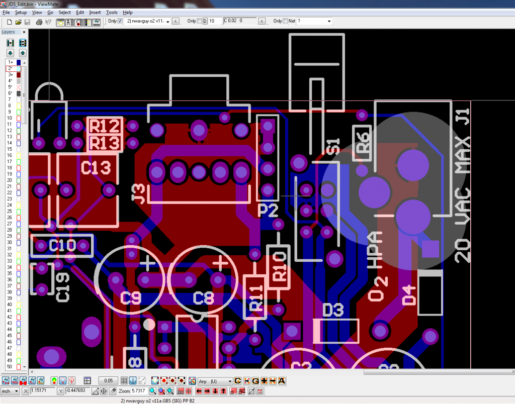
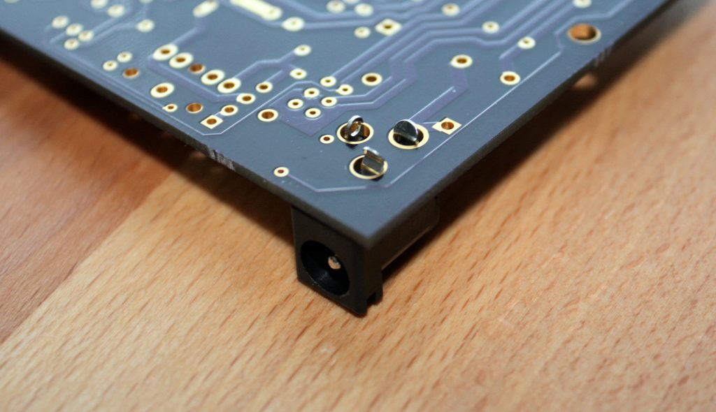
This test proved that T8 only affects holes at the DC jack. Thus, I changed T8 in the drill file to our desired hole diameter of 120mils (3.05mm). Here’s the visible result, showing successful 3mm, plated holes at the power jack:
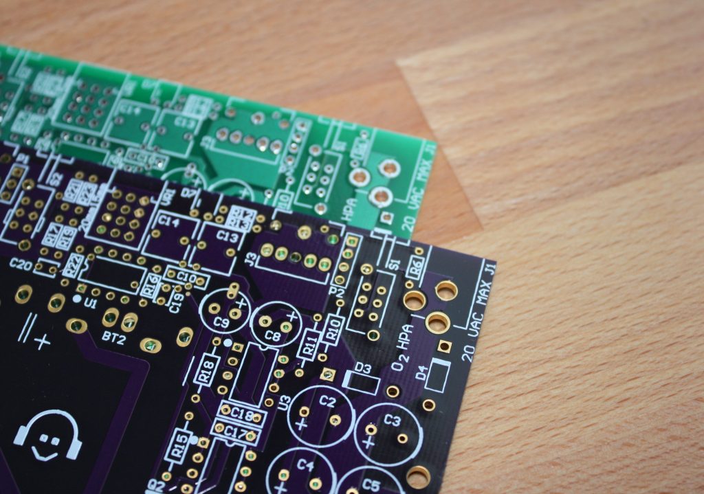
O2 v1.1b PCB fabricated and confirmed perfect!
AVAILABILITY
Modified O2 PCBs are Now in Stock. You may also download the v1.1b Gerbers for your own use.
SUMMARY
O2 v1.1b is a straightforward manufacturing alteration to the O2 v1.1a circuit board. Specifically, holes of the power jack, J1, have been enlarged to accommodate standard power jacks. All aspects of the Objective2 remain unchanged from NwAvGuy’s work. The PCB layout is identical. Performance is identical. Even the silkscreen still shows “v1.1a” (admittedly confusing). The O2 v1.1b PCB merely allows builders to assemble O2 without encountering frustration from the DC jack.
Great work to keep the O2 free of part issue. I am sure NwAvGuys will understand it as well.
Uh, so which part is the replacement to Kobiconn 163-7620-E with the new PCB? I’m confused.
Anon: The board change accommodates all standard 2.1×5.5mm jacks. If shopping at Mouser, their suggested replacement part works well: 163-7620E-E
Are there any plans for alternate soldermask colors?
Paul,
What color would you like to see?
The purple in this blog (also seen on NwAvGuy’s blog) looks really nice. Given any choice of common solder masks I’d choose black with a white silk screen.
Excellent rework through the gerbers. Believe the following Adafruit DC power jack will fit the original PCB holes as the pin widths are suited for breadboards @ 3 x 1.0mm:
https://www.adafruit.com/product/373
DC power jack is from CUI p/n PJ-102AH
Digikey p/n CP-102AH-ND
http://www.cui.com/product/components/connectors/dc-power/jacks/2.0-mm-center-pin/pj-102ah
http://www.digikey.com/products/en?keywords=PJ-102AH%20
http://www.futureelectronics.com/en/technologies/interconnect/connectors-pcb/dc-power-jacks/Pages/6028101-PJ-102AH.aspx?IM=0
I just installed the Adafruit power jack Kumar suggested into the original PCB. It fit perfectly!
Thanks Kumar!